Why is my machine running hot? Again?
08/29/2024
It is unfortunately all too common in industrial plants to have machines suffering from high temperature conditions. Often, the same machines have repeat problems, even after changing parts or taking other steps to remedy the situation.
To solve these problems, it helps to have some understanding of heat exchanger application basics and how their use in real world situations can be assessed and improved; moreover, not every high temperature condition is a heat exchanger problem! Note this is not a formal treatise on heat exchanger design or applications. Instead, the following observations are intended to help plant personnel better identify high temperature causes and solutions instead of blindly replacing parts and hoping for the best.
Industrial Heat Exchanger Applications Overview
Heat exchangers are critical components in many industrial devices including air compressors, hydraulic machines and many other machine and process cooling applications. Of course, they are also inextricable parts of the cooling system equipment itself – chillers and cooling towers are literally heat exchangers with associated components. Fortunately, cooling system equipment is usually designed for easy maintenance and includes robust capacity relative to the heat loads.
Process machine heat exchangers, on the other hand, are designed to perform the needed machine cooling at reasonable cost and under normal conditions. The compromises often include heat exchanger type and location on a machine, which, in turn, substantially affects the maintainability of the heat exchanger over the life of the machine.
Common industrial machine cooling applications are typically oil cooling (either lubricant or hydraulic), which are typical in many industries on air compressors or machine gearboxes, and closed loop, treated water cooling for plastic molds, extruder barrel cooling systems and calendar roll stands. This article will use the closed loop, oil cooling application as the prototypical assumed case.
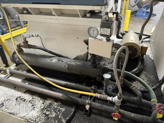
Gearbox oil cooler equipped with thermostatic control valve (in box with gauge) and leaving oil temperature sensor in fitting at other end of heat exchanger.
It is, unfortunately, quite common in plants to have high machine operating temperatures. Some equipment will fault from internal protective functions (e.g., air compressors) while others without these protections may continue to run but with highly undesirable outcomes. These can include significant damage to the machine (and expensive repair costs) and/or production of bad parts (which are costly to replace and may result in customer issues).
Remembering that equipment manufacturers are trying to provide adequate cooling for unknown and uncontrolled circumstances (in that they have little control over how a machine is actually cooled once in the customer’s hands), they use two approaches – cooling design and cooling medium specifications.
First, they design the cooling systems for what are typically considered “near worst case” applications, so they can handle challenging but not impossible situations.
Second, they specify the minimum required cooling water conditions (temperature and pressure) conservatively so problems are unlikely if those conditions are maintained. This can be seen in temperature and flow requirements that calculate out to higher heat loads than the machine can produce, minimum required supply pressures much greater than the machine's design pressure drops at rated flows and other inherently padded requirements.
Before going into recommended evaluation steps, a brief review of heat exchanger basics will help put the suggestions in context.
Heat Exchanger Fundamentals
There are a wide variety of heat exchanger designs and features that are beyond the scope of this article. Different types provide for heat exchange between different mediums (such as water to water, air to water and oil to water) and different pressures. The basis of this article is that the type of heat exchanger is already decided by the machine manufacturer and the plant is simply trying to get the system to perform properly.
For any given heat exchanger (HX) application there are several variables that govern the performance of the system:
• Hot side entering temperature
• Hot side flow rate
• Cool side entering temperature
• Cool side flow rate
• Heat exchanger effectiveness
HX effectiveness is a roll-up term that encompasses multiple factors for simplicity. Again, given that the design of the HX is already selected, including materials and thicknesses, physical features (smooth surfaces, fins) and flow paths, effectiveness basically boils down to “is it working like it should given the temperature and flow conditions?”
It must be remembered heat exchangers are exactly that – exchangers – so the heat being removed from one side is invariably the same as the heat taken in by the other side. In other words,
Hot side heat out = Cool side heat in
Recognizing the equality requirement can be helpful to troubleshooting high temperature problems. This can be considered by answering three questions:
1. Is the machine heat being delivered to the heat exchanger?
2. Is the heat exchanger capable of transferring the heat?
3. Is the cooling system properly removing the heat?
|
Heat Transfer Equation Calculations The heat flow (whether in or out but always from high to low) is described by the equation: Q = U X A X (Tin - Tout) which for our interests in analyzing high temperature conditions is significantly simplified because of the existing situation we are evaluating. A, for the heat transfer surface area, is defined by the existing heat exchanger. (Tin - Tout) become defined in the operation and, as we will see, can be affected by application characteristics. U is the overall heat transfer coefficient, and this is the part that can get squirrelly. U is a function of several factors including the fluid properties involved, the material(s) used in the heat exchanger, the material thickness and the surface shape (smooth, grooved, finned), which, again, are predefined in a given application. However, there are a couple factors that are variable in operation. The first is the fluid velocity over the surface, and this is a critical part of the calculation. The simplest way to comprehend this is to recognize (with extreme simplification of the math for a water-to-water application): Hot side GPM X (Hot Tin - Hot Tout) = Cool side GPM X (Cool Tin - Cool Tout) The other variable aspect of U is the thermal conductivity, or the heat transfer capability of the HX. Technically, this does not change as the HX material and design are constant, however any surface fouling that occurs has the effect of changing the realized thermal conductivity. While they would be precisely analyzed as two separate layers of HX material, for our practical evaluation we can treat the HX material and any changes to it caused by surface fouling as a single property. Consequently, when analyzing a high temperature situation, we have to consider both the heat exchanger condition (i.e., any fouling or area reduction from blocked tubes), as well as the medium conditions including the entering and leaving temperatures and also the flow rates and fluid velocities on both sides. |
Heat Exchanger Fouling and Mitigation Methods
One common cause of poor HX operation is fouling, described as the accumulation of unwanted substances on the surfaces of heat exchangers. The unwanted substances could be mineral scales, sediment, corrosion products, organic matter or biological growth, and may occur alone or in combination. Fouling is like putting a layer of insulation on the heat exchanger surface. It frequently leads to compounding conditions that get progressively worse with accelerating bad performance.
Fouling is frequently the issue when HXs have acceptable temperature and flow conditions but do not provide good cooling. However, while it is a frequent cause of poor machine cooling, it is not the only cause. Many other factors can cause machine cooling issues besides fouling and it is vital but sometimes difficult to determine the underlying cause of high machine temperatures.
Heat exchangers can sometimes be cleaned but, depending on the heat exchanger design, it can be difficult to completely remove minerals and other contaminants. Consequently, the typical response is to replace the heat exchanger. While the new HX will often improve the conditions, in other cases it will not last or the problem will continue unabated, leading to frustrating situations.
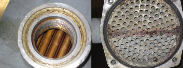
Oil cooler showing clean tubes on oil side and mineral fouling on water side. Thin layers of scale significantly impact cooling. Note more scale is on the warm leaving water half (bottom).
Consistent and appropriate water treatment practices are critical to control heat exchanger fouling. Consistency is critical as poor-control events allow fouling conditions to start, which then become progressively worse over time. Note that the same treatment program that is fine for chiller condensers may not be good at all for air compressors or other higher temperature cooling applications, as potential for mineral scaling increases with operating temperature. Condensers practically never see hot-side temperatures over 100 to 105°F (38 to 41°C) while air compressor HXs may regularly face hot side temperatures of 200°F (93°C) or higher.
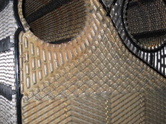
Sediment on the open loop side of an isolation plate heat exchanger before cleaning. This material was kept out of the plant machine heat exchangers.
Because it’s nearly impossible to eliminate fouling in open tower water systems, Integrated Services Group (ISG) strongly recommends converting to closed loop systems isolated behind parallel, redundant plate heat exchangers for tower water cooling applications (the redundancy supports cleaning one HX at a time with continuous operation). Our clients using these systems, which limit the dirty open loop tower water to one side of the isolation HXs, report vastly fewer problems with the various heat exchangers scattered throughout their facilities. This is due to both the improved water quality in the machine-side closed loop and the temperature-limiting effect at the point of the tower water heat exchange – the open loop tower water never sees the high temperature HXs and instead is only cooling the blended temperature closed loop water.
Machine Operation Observations
Keep in mind that machines can’t store heat in any meaningful amounts – heat in must equal heat out. Any machine with zero cooling will overheat quickly, potentially with catastrophic results. Long before that point, a machine will simply run hotter as the temperatures rise to an equilibrium condition where the heat being generated is transferred to the cooling medium (i.e., the Tin - Tout part of the heat transfer equation gets larger).
The time frame of overheating is typically in minutes. Documenting the operating conditions over time, particularly when a machine or its heat exchanger are new or recently cleaned, can be extremely helpful in evaluating these situations.
Field Checks and Typical Heat Exchanger Operating Conditions
Machine cooling condition readings should include as many of the following as possible:
• Entering cooling water temperature
• Leaving cooling water temperature
• Cooling water flow (if available)
• Entering cooling water pressure (if flow is unavailable)
• Leaving cooling water pressure (if flow is unavailable)
• Supply and return header pressures
• Machine operating load (%, amps, other indication as available)
• Machine internal temperature(s)
• Machine internal valve positions, cooling loop flow control settings
Most plants don’t have portable flow meters or good access to the flow piping, but it is helpful to make flow readings along with the temperatures and pressures listed above. Actual flow readings can be used with current and future pressure readings to correlate flow values when the meter is not installed.
Under normal conditions, the cooling water temperature should change by ≈10 to 15°F (6 to 8°C), e.g., in at 80°(27°C) and out at 90 to 95°F (33 to 35°C). This should match up with a pressure drop of around 12 to 20 psi (0.8 to 1.4 bar) for gauges connected immediately adjacent to the machine after any strainers or flow balancing devices (such as circuit setters).
Pressure drop through an inline strainer should not exceed 3 psi (.2 bar) in normal operation and should be 2 psi (.1 bar) or less when clean. For properly designed piping systems, the pressure at the supply and return headers to the machine drop should be 20 to 30 psi (1.4 to 2 bar) apart, or something like 60 psi (4 bar) supply, 30 psi (2 bar) return.
Piping drop pressure losses are efficiency penalties that don’t provide any value to the plant. If the drop piping is made larger, for example using 2 1/2-inch vs. 2-inch (i.e., one or two sizes larger in under 2-inch pipe and one size larger when over 2 inches), then the system can be run at lower pressures with significant pumping efficiency improvements. In many plants, 50% or more of the pressure required is for distribution losses, while in a high efficiency system the distribution losses can be less than 20%.
Be sure to use high quality temperature sensors and pressure gauges. See the Chiller & Cooling Best Practices Magazine article “Vital Signs: Critical Instrumentation for Cooling System Health” (Sept. 2023) for more information on selecting and using instrumentation for cooling and other utility systems.
Common Heat Exchanger Problems
When trying to troubleshoot high machine temperatures, the following are common potential causes:
• Heat exchanger fouling
• Warmer cooling water
• Reduced cooling water flow
• Increased machine heat load (higher running conditions)
• Internal cooling system issues
Fouling: While fouling is a common cause, it should be investigated along with the other cooling-side factors below, rather than assumed to be the issue.
Elevated cooling water temperature: Warmer cooling water can occur from seasonal swings in tower-cooled systems, but these temperatures shouldn’t be an issue with proper flow. Variations above normal may occur from failures in the cooling water loop such as loss of a tower fan or low tower water flow, and tower water supply temperatures above 87 to 90°F (31 to 32°C) are likely to cause problems. Also, switching machines from chilled water to tower water can reveal problems or even resurrect them, as many times machines are shifted to chilled water due to high temperature problems. However, chilled water cooling is much more costly (typically five to eight times) and the machine cooling is almost certainly designed for operation at tower water temperatures, so cooling with tower water is preferrable if possible.
Cooling water flow problems: Reduced cooling water flow is possible from multiple causes upstream and downstream of the machine and the heat exchanger. High temperature situations can arise from any of the following whether alone or in combination:
- Excessively long cooling water piping
- Too small diameter cooling water piping
- (Note these first two are related – larger piping can offset greater length)
- Corrosion and/or other obstructions in piping (clogged strainers or filters)
- Too many devices connected to piping/taps/main header
- Partially closed valves or other devices in the line
Recognize that overall circumstances for a machine can change as new machines or other devices on the system are added, even with no changes to the original machine or its supply piping.
Increased machine heat load: The cooling system may be working perfectly but machines may experience high temperatures due to increased loading generating additional heat. This is generally unlikely with packaged equipment such as air compressors, but can occur with custom assembled systems such as extrusion line gearboxes being run faster for greater throughput. It may also occur where the machine has been running at a lower heat load (for example a lower discharge psi or bar) and is changed to a higher output where the previously marginal cooling was adequate but is not sufficient at the higher running load.
Internal cooling system issues: Because many machine cooling applications have closed hot side systems with oil or specially treated water, the closed side of heat exchangers are much less prone to fouling (at least compared to cool side fluids). The internal cooling system, which may include throttling or three-way valves, would be looked at after the other potential causes were evaluated and ruled out. Internal cooling system side issues are fairly rare, and while they can and do occur, they aren’t the place you normally look first.
Machine Cooling Troubleshooting Examples
Now that the different aspects of heat exchanger operation have been discussed, reviewing several machine cooling scenarios should help illustrate the effect various factors can have on cooling and high temperature conditions.
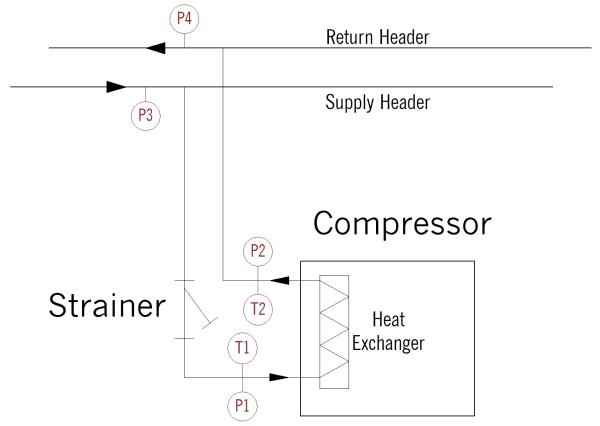
Schematic of air compressor cooling system in troubleshooting examples.
The following examples are all based on the system shown in the schematic drawing. An air compressor is cooled with water supplied from a nearby header that originates some distance away in the plant. There is a Y strainer in the drop to the compressor, thermometers in the drop and pressure gauges in both the drop piping and in the header pipes.
Example #1
Situation: An air compressor is running hot after getting progressively warmer over the last several months. Sometimes the compressor can run right at the high temperature limit, but at other times it exceeds the recommended running temperature, occasionally tripping off due to high temperature.
Conditions when examined:
T1 – Entering water temperature: 82°F (28°C)
T2 – Leaving water temperature: 94°F (34°C)
P1 – Entering water pressure: 46 psi (3.2 bar)
P2 – Leaving water pressure: 29 psi (2 bar)
P3 – Supply header pressure: 56 psi (3.9 bar)
P4 – Return header pressure: 23 psi (1.6 bar)
Analysis: The temperature difference is 12°F (6°C), which is a reasonable change. The pressure drop through the machine is 17 psi (1.2 bar), which is also typical. The supply pressure decrease from the header to the machine is 10 psi (0.7 bar), which is slightly higher than desired but may reflect a partially fouled Y strainer. Given that the cooling side metrics look good, the problem with this machine is likely fouling in the heat exchanger. The gradual increase in air compressor running temperature is concurrent with classic fouling over time getting worse.
Example #2
Situation: An air compressor is running hot after operating well for several years. A new compressor was added in the compressor room in the early spring and the temperatures on both are seen to be running warmer into the summer. The piping coming into the room has been installed for over 20 years and is unchanged except for adding the other compressor.
Conditions when examined:
T1 – Entering water temperature: 83°F (28°C)
T2 – Leaving water temperature: 105°F (41°C)
P1 – Entering water pressure: 41 psi (2.8 bar)
P2 – Leaving water pressure: 36 psi (2.5 bar)
P3 – Supply header pressure: 45 psi (3.1 bar)
P4 – Return header pressure: 34 psi (2.3 bar)
Analysis: In this case, the temperature difference is 22°F (13°C), which is well above typical design conditions. Conversely, the pressure drop through the machine is only 5 psi (0.3 bar), well below normal. Both this and the in/out temperature difference point toward low cooling water flow. Supporting this, the header supply pressure is lower (45 psi vs. 56 psi or 3.1 bar vs. 3.9 bar) and the return psi/bar is higher (34 psi vs. 23 psi or 2.3 bar vs. 1.6 bar). These two indicate more total flow and greater pressure loss in the main header pipes. This makes sense given the new air compressor being added and drawing its own cooling water flow without any change to the header pipes. The new compressor also shows warmer temperatures but is not alarming, likely due to its new heat exchanger. The solution is enlarging the supply and return piping for greater cooling flow and possibly replacing the drop piping to the original compressor, if it’s in poor condition.
Example #3
Situation: An air compressor is running hot after operating well for several years. A new compressor was added in the compressor room in the early spring. The new machine is running fine but the original compressor was noticed to be running warmer into the summer and now is tripping off on high temperatures. The piping coming into the room has been installed for over 20 years and is unchanged except for adding the other compressor.
Conditions when examined:
T1 – Entering water temperature: 83°F (28°C)
T2 – Leaving water temperature: 105°F (41°C)
P1 – Entering water pressure: 33 psi (2.3 bar)
P2 – Leaving water pressure: 28 psi (2 bar)
P3 – Supply header pressure: 53 psi (3.7 bar)
P4 – Return header pressure: 26 psi (1.8 bar)
Analysis: In this case, the temperature difference is again 22°F (13°C) and the pressure drop is only 5 psi (0.3 bar). Together, these point to reduced flow through the air compressor. However, the header pressures are relatively unchanged from the original conditions and the new compressor is not having any high temperature issues, as would be the case with insufficient cooling water supply. The key indicator in this case is the large pressure drop from the supply header to the compressor inlet: 20 psi vs. 10 psi (1.4 bar vs. 0.7 bar) in the original case. More importantly, it is 20 psi vs. only 4 psi (1.4 bar vs 0.3 bar) drop in the low flow case where the reduced header pressures caused the lower flow. The high pressure drop occurred due to the strainer being plugged with pipe debris knocked loose in the work adding the new compressor cooling drop. Clearing the strainer solved the immediate problem but the compressed air piping should be closely examined for corrosion and possibly replaced.
Example #4
Situation: An air compressor is running hot after a service visit several months ago. It was noticed to be warmer during cool weather, but as ambient temperatures have warmed the compressor is getting excessively warm and shutting down.
Conditions when examined:
T1 – Entering water temperature: 82°F (28°C)
T2 – Leaving water temperature: 89°F (32°C)
P1 – Entering water pressure: 46 psi (3.2 bar)
P2 – Leaving water pressure: 29 psi (2 bar)
P3 – Supply header pressure: 56 psi (3.9 bar)
P4 – Return header pressure: 23 psi (1.6 bar)
Analysis: The temperature difference is 7°F (4°C), which is low, however the pressure drop through the machine is 17 psi (1.2 bar), which is typical. The supply and return header pressures also are normal. Together, these point to normal cooling flow but reduced heat transfer into the cooling water. Examining the air compressor revealed that the oil cooling control valve actuator was damaged during the service resulting in choked oil flow through the closed side of the heat exchanger. When the cooling water was cool enough from outside conditions, the compressor stayed within satisfactory limits, but when the cooling water warmed up it could no longer stay within allowable conditions. Repairing the valve control mechanism fixed the oil flow to the HX and solved the problem.
Conclusion
Machine cooling high temperature problems are unfortunately all-too common in industrial plants. While the initial suspect is always the heat exchanger, there are several other factors that can be the underlying cause. Important steps can be taken to minimize the potential for heat exchanger fouling, but when problems do occur, careful examination of the machine and the system can help identify the problem efficiently and with minimal wasted effort.
Please contact the author with any questions or comments. As may be guessed, this article reflects lessons learned from numerous real-world examples. I would be grateful to hear any reader experiences of these type problems and Hard Knocks U-learned solutions.
About the Author
Clayton Penhallegon, Jr.is the Managing Member of Integrated Services Group, which specializes in industrial cooling water system operational effectiveness and cost reduction. He has worked for over 35 years with various industries including plastics, paper, wood products, metal containers and textiles. He holds a Bachelor of Mechanical Engineering from Georgia Tech, an MBA from Georgia State University and is a registered PE in Georgia.
About Integrated Services Group
Integrated Services Group performs industrial cooling water system operational effectiveness and cost reduction technical services. Its services include system assessments, new and upgrade system design, system start-up and retrocommissioning, and high efficiency control design and implementation. ISG celebrated its 25th year anniversary in 2022 and serves clients throughout the USA and North America. For information, visit https://www.isg-energy.com.
For similar articles on Cooling Controls System Assessments, please visit https://coolingbestpractices.com/system-assessments/cooling-controls.
Visit our Webinar Archives to listen to expert presentations on Cooling Technology at https://coolingbestpractices.com/magazine/webinars.