NOTE: This is the second of a two-part article on the critical requirement for holistic system controls to achieve the highest cooling system efficiencies. Part 1, printed in the January/February 2024 issue of Compressed Air Best Practices, laid the groundwork for this discussion by describing widely found control designs and operations, as well as common weaknesses in those applications. Readers are encouraged to review that portion before reading Part 2, as the information presented here presumes familiarity with the definitions and general application concepts presented in Part 1. Building on that introduction, this article will describe integrated “holistic” controls and present representative applications showing how they result in superior cooling system efficiency.
Part 1 of this article described three factors of process cooling system efficiency (equipment selection, system implementation and system operation) and all three must be in optimal condition to have the highest efficiency. System operation was also noted to be a combination of both the system controls functions (or lack thereof) and plant operating practices.
Many forums address the first two components of the high-efficiency triad. Product manufacturers frequently tout the increased efficiency of their latest products and engineering design articles regularly discuss the benefits of various system design features, including several by this author in previous editions of this same publication.
Furthermore, the third aspect of efficiency, system operation, is periodically recognized as important in its own right, and various presentations are made that cover different facets of controlling and operating systems. However, while this third component is not ignored, it is fair to say that system operation, and in particular the controls functions portion, is not set apart for the truly decisive impact it has on system efficiency.
The Criticality of Controls
The importance of the controls’ performance to overall system efficiency cannot be overstated. In fact, outstanding controls can wring higher efficiency out of an average system (hardware and design) than a highly efficient system can achieve with poor controls. This may be difficult to accept, but there are good explanations for why this is true.
First, after years of efficiency awareness, the difference between standard and high efficiency equipment is often modest (perhaps 5 – 10%); similarly, system design differences may be responsible for another 5 – 15% efficiency improvement. As stated in the previous article, high performance controls and operating strategies can deliver 35 – 50% efficiency savings with the same equipment and system design (more explanation of this later).
Second, as cooling conditions are inescapably variable over time, the control operation of the equipment is the critical factor in system efficiency. Most plants have varying cooling loads as lines are started and stopped, molds changed, PMs performed, etc. and these result in variable loading on the cooling system. Even in cases with atypically flat loads (such as data centers), cooling systems as a whole exist in dynamic ambient environments; consequently, significant opportunities exist to exploit the off-design conditions present the majority of yearly hours.
Finally, cooling systems with high performing controls strongly correlate with recognized best practices operation of the plant. The controls capability enables and supports the operators in managing the cooling system proactively so equipment is maintained (filters are cleaned, bearings are lubricated), equipment that is due for scheduled maintenance or needs repair gets handled promptly to again be available for operation and opportunities to improve the operation can be identified and qualified through the system data display and trend data analysis.
In situations where all the high-efficiency elements are present, the overall improvement in efficiency can exceed 50% of the base system operating efficiency. Note that this is specifically referring to industrial process cooling systems, not commercial building HVAC systems—while the same techniques and concepts apply, commercial systems’ loading is nearly always closely tied to weather conditions and therefore they are not as able to capitalize on the off-season ambient conditions existing for year-round industrial applications.
Holistic Systems Controls
The previous article presented the concept of system controls that span the complete cooling system. To recap, this means a single or consolidated control platform that controls the entire cooling system including the various interconnected sub-systems, including chillers, pumps, cooling towers, and free cooling heat exchangers. Comprehensive system controls also provide HMI functions including status displays, fault alarms and data trending and reporting. Altogether, system controls should reduce operator workloads and support potential efficiency improvements.
The earlier article also introduced the term “holistic” system controls which are high performance system controls that constructively integrate the interaction effects of the linked sub-systems. It cannot be emphasized enough that simply having system controls does not mean they function holistically.
To further clarify the scope of holistic controls, they include both the programmable controls and functional logic to control the equipment operation as well as the VFDs, sensor inputs and other physical interfaces to effect the operations. Practically speaking, every motor load in a holistically controlled system should be on a drive to support the control functions and provide other benefits of drive operation¹ , and this continuing discussion assumes drive control capabilities on all relevant applications.
The previous article also observed that the complexity of the linkage between sub-systems was both the challenge to higher efficiency and the source of the efficiency improvement opportunity.
Holistic controls purposefully manage the operation of the cooling sub-systems to aggressively extract savings from the various components. This means holistic controls frequently trade sub-system energy use between different portions of an overall cooling system to get the highest total efficiency. Critically, this must be done with due care to ensure the efficiency improvements don’t come at the expense of effective process cooling—we can’t have the tail wagging the dog!
While this sub-system leverage may occasionally happen in standard system controls, for example when cooling tower setpoints are lowered for better chiller efficiency, holistic systems will closely manage conditions and equipment to achieve notably higher efficiency. In the cooling tower setpoint example, holistic systems might also use the following functions:
- Tower setpoint lower than the chiller manufacturer’s normal minimum recommendation when possible but floated up to the tower design temperature when required by outdoor conditions
- Condenser pump flow control based on chiller refrigerant differential pressure
- Centrifugal chiller inlet guide vane position monitoring to trim the degree of tower setpoint adjustment²
By combining these three control functions, the tower fan runs only as needed in warmer outside conditions, and the condenser pumping and chiller energy are optimized with minor increases in tower fan energy when it’s cooler outside. Overall annual tower fan energy is saved by not running to an unattainable setpoint in summer even with the modest increases in the cooler months. The condenser pumping power may be reduced by 25 – 40% or more while the chiller energy use is either the same or trimmed modestly, and this is on top of the basic chiller energy savings from a lower condenser water temperature.
To highlight the insignificance of the cool season tower fan energy changes, consider that for running a fan at 30% speed vs. 20% speed (a typical premium for lower leaving water temperature in cool conditions), the incremental fan power is just under 2% of the full speed fan power—and this on what is typically the smallest portion of the overall system power. The calculations are illustrated below.
Fan power at 30% speed as fraction of full speed power (see sidebar on the fan and centrifugal pump affinity laws if these are unfamiliar):
(Speed2/Speed1)^3=(Power2/Power1)
or in this case:
(0.30/1.00)^3=(Power2/Power1)
Solving for Power2, we get
Power2=0.027×Power1=2.7%
Similarly, the power for 20% speed is
(0.20/1.00)^3=(Power2/Power1)
Solving for Power2, we get
Power2=0.008×Power1=0.8%
As a result, the power penalty to run the fan at 30% instead of 20% is
2.7%-0.8%=1.9%
For a typical system where the fan power is typically under 10% of the total HP, this would represent around 0.2% of the nominal full power requirement.
Standard System Controls vs. Holistic System Controls Functional Comparisons
The following table lists typical cooling sub-systems and the control functions applied in standard and holistic control systems. Note these are broadly representative of common industrial systems but there are many variations and functions not listed in this article.
| Sub-system | STANDARD SYSTEMS | HOLISTIC SYSTEMS |
| Tower Fan(s) | Single setpoint | Setpoint float on ambient conditions |
| Condenser Pumps/Open Tower Water Pumps | On/off operation | Speed varied in relation to water temperature |
| Chiller Recirc or Primary CHW Pumps | On/off operation | Speed varied in relation to water temperature and/or total process cooling loop flow functions |
| Process CHW or Secondary CHW Pumps | On/off operation, or pressure in mechanical room controlling pump speed | Speed varied based on one or more remote differential pressure sensors (as needed by system design) |
| Chillers | Staged on & off on chiller amp loading % | Staged on load % with part-load considerations and delta-T mgt. for higher efficiency loading |
| Process/Machine Open Loop (Tower) Cooling Pumps | On/off operation | Speed varied based on closed loop temperature with temperature setpoint varied in relation to tower water temperature |
| Process/Machine Closed Loop Cooling Pumps | On/off operation | Speed varied based on one or more remote differential pressure sensors with pressure setpoint varied in relation to water temperature |
| Sensor Suite | Minimal points needed for operation | Enhanced point list for system operation characterization and control point redundancy |
Beyond the general concepts listed in the table, there are numerous implementation details that characterize fully functional systems such as non-overlapping centrifugal separator blowdown schedules, water metering for usage monitoring and fault conditions and automatic pressure sensor blowdown control. Unsurprisingly, these are tailored to specific system requirements.
Systems Controls Offset of Design Limitations
As stated earlier in the section on the critical importance of the controls to total system efficiency, high performance controls can adapt for less than ideal system design, and it’s in these functional differences that the adaptation takes place. For example, an extremely common standard system design and controls feature is constant speed pumping to tower and chiller recirculation loops (this occurs often even in systems with variable pumping to the process cooling loads).
To rectify these situations, high performance controls will include logic that in some way ties the recirculation loop flow to the process loop flows. There are multiple approaches that can be used depending on the specifics, such as using a fixed speed ratio for the recirc pumps to the process pumps or linking the loop delta-Ts, but whatever method is used will reduce the recirc loop pumping.
Even a modest 10% reduction from full speed will save around 25% of the pumping power (see the Affinity Laws sidebar) and potentially more if there are partially closed valves on the recirc pump loops (a common occurrence at pump discharges and other loop locations). Moreover, the power savings reduces the motor heating, bearing and coupling loads and seal pressures, all of which extend the life of the pumps and lower the maintenance requirements.
These benefits substantially offset the efficiency penalty in the suboptimal design at modest cost and without requiring significant reworking of the piping or other major changes. Note that a better initial system design would yield still better efficiency and would have cost less to install to begin with, but at least all is not lost if intelligent controls are implemented as described.
Holistic Systems Controls Implementation Distinctions
In addition to the simple “yes or no” questions on the presence of various advanced control functions, Holistic controls also include concentrated focus on the how of the implementation, and correctly doing the how requires knowledgeable and focused implementation personnel.
As noted, the majority of cooling systems, and thus the experience base of most control engineers and technicians, are commercial HVAC systems. Industrial process cooling is different in key use aspects from commercial systems, most critically in the regular presence of meaningful load changes—process cooling loads often change in significant steps (such as when lines start and stop) vs. the general daily rise and fall characterizing many commercial air conditioning loads—and close control must be maintained over the cooling process during these changes. Commercially grounded personnel are frequently not attuned to the demanding requirements of process cooling and will unknowingly employ unsuitable control approaches in industrial systems.
To the contrary, the capabilities provided by dedicated industrial controls specialists through holistic controls should actually improve the process cooling effectiveness by making the cooling more uniform, even while efficiency improves. Consider the following comparative examples:
| APPLICATION: Cooling Tower Fan Control | IMPLEMENTATION | RESULTS |
| Standard System Controls | Single temp sensor, remote from discharge (installed where convenient, such as in a tank or pipe inside a building) | Long response delays due to flow lag and blending effects, extreme hi-lo fan cycling, ±5° temp swings |
| Holistic System Controls | Individual cell temp sensors in immediate discharge pipes from tower cells | Much closer control <±1°, individual cell response for better loading³ |
| APPLICATION: Chilled Water Pump Control | IMPLEMENTATION | RESULTS |
| Standard System Controls | On/off (no pressure) control only or single pressure/DP near pumps | Pressure deviation of ±10% to 30% based on lines running and pump mix |
| Holistic System Controls | Differential pressure sensed in midst of loads, multiple points if needed | Greatly improved pressure stability to lines, typically less than ± 5% total |
| APPLICATION: Free Cooling Transition Ctrl | IMPLEMENTATION | RESULTS |
| Standard System Controls | Typical commercial system transition—stop chillers, lower tower water temp, change valves to FC HX | No net cooling to process during cooldown or warm-up transition back to chillers, cooling water temp rise of 5 - 15°, variable duration spike |
| Holistic System Controls | Chillers kept on through tower water cooldown, FC HX pre-cooled, transition completes once temp reached using proportional control valves for change | Continuous process cooling through transition, temp swing usually < 2°, process flow consistent during transition due to pressure control of pumps |
Like these examples, many typical commercial applications approaches have poor efficiency, poor stability, or both in industrial use. As cooling for process operations, uniformity of the cooling is (or at least, should be) paramount in the cooling system operation; and operating efficiency should be as good as it can while still meeting the production requirements. Producing 10,000 plastic forks with the tines pointing inward due to cooling water temperature spikes is not acceptable!
As illustrated in the examples, a key focus with holistic controls is locating the sensors where they most accurately indicate the system conditions, which then enable the controls to more effectively manage the operation. The common practice with many system installers is to place sensors where convenient and only install the minimum points necessary for the control methods used, and while these are functional at a base level, they do not support optimal system performance.
Unfortunately, poorly implemented systems are common. One frequent condition with standard system controls (along with the No Controls and Standalone Controls systems) is maintaining somewhat uniform cooling by excessive equipment operation—having more pumps running than needed much of the time, for example, with the result that equipment is run harder and longer than otherwise needed and hence requiring more maintenance and more frequent replacement. What is often counterintuitive about holistic controls is that the enhanced performance not only meets the process uniformity requirements, it also provides the highest possible efficiency and related maintenance and equipment life savings.
Assessing Incumbent Controls Systems
So how does a system owner or operator determine if they have holistic system controls? In part this can be determined by just looking, but it then gets more complicated as appearances alone don’t tell the whole story.
In our framework of controls categories—No Controls, Standalone Controls and Standard System Controls—the first two can be somewhat determined visually. Recall that No Controls is either literally no system controls, just On/Off switches or their equivalent, or single device unit controls such as on an air-cooled chiller that are integral to the device; in other words there are no controls applied to the equipment externally. Standalone Controls refers to external and frequently multi-device controls that are dedicated to a single function (e.g. cooling tower fan control) or functional group (such as a pressure controller on a pump skid with on-board controller and pump VFDs).
These system types by definition are not system controls, and if there are no overall controls—no main HMI interface, no controller(s) performing equipment control of essentially all the cooling system components—then there are no system controls and certainly no holistic system controls.

Typical standalone control system with on-skid pressure sensing and pump VFDs.

Remote differential pressure sensor installation.
If a plant does have System Controls as defined in this context, determining if they are Standard system controls or Holistic controls is necessary to consider the potential for improvements.
Self-Assessment Questions
To rephrase the comparison of standard system controls and holistic systems, both system types have control over more or less the entire cooling system; consequently, the distinction is one of functional depth versus span of coverage. If a cooling system has system controls, the following are conditions to look for and review with your system operators and/or vendor technical support to assist in determining whether the potential exists for more effective controls:
- When it’s cool outside, do tower water temperatures regularly cycle from higher to lower values?
- When it’s warm outside, do tower fans run continuously while the tower water temperature floats up a few degrees through the day and down over night?
- Are there VFDs on pumps that run in hand and/or that run under control constantly at or near full speed (55-60 Hz output frequency)?
- Are there VFDs that regularly oscillate between higher and lower frequencies, for example 48 Hz and 42 Hz up and down every 5-10 seconds continuously?
- Are there pumps and flow loops that run constantly and continuously regardless of variations in cooling load (such as the number of lines running or daily throughput)?
- Do multiple chillers routinely run at low loads or, conversely, high loads with CHW temperatures floating above desired setpoints?
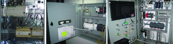
Which control system is holistic? Can you tell by appearances? It’s the one on the right but there’s no obvious distinction from just looking.
These same questions can be used to evaluate potential cooling control systems for new projects by rephrasing them as functions that should be present in a new system and as performance standards against which an operating system will be reviewed. If a vendor is uncertain about the concepts or unfamiliar with methods to install these functions, then perhaps they aren’t the folks you should be working with.
Pump and Fan Affinity Laws Power CalculationsPropeller type fans and centrifugal pumps in closed loop systems generally follow a set of equations for their speed, flow, pressure and power as long as they stay in an applicable range and system configuration. These equations, known as the Affinity Laws, apply to changes in speed and fan or pump impeller diameter, however we will only address the speed implications here since our scenarios are based around using VFDs for speed changes and not for impeller diameter modification (typically trimming). The equations are: Speed1∝Flow1 Speed2∝Flow2 (Flow2/Flow1)^2=(Pressure2/Pressure1) (Flow2/Flow1)^3=(Power2/Power1) When applied to a modest speed reduction for a pump from 100% to 90% we get these results: (0.90/1.00)^3=(Power2/Power1) Solving for Power2, we get Power2=0.729×Power1=72.9% or roughly 73% of the initial power requirement. Assuming around 3% losses in the VFD, the 10% speed reduction saves approximately 25% of the initial power; obviously greater speed reductions would generate even more savings. In cases with pumps where there are partially closed system valves either for pump motor amp limitation and/or loop flow settings, use of VFDs would save even more along with the separately mentioned benefits of improving the motor and driven load operating conditions (such as lower temperatures, lower bearing and coupling loads or lower seal pressures). |
Conclusion
Cooling system controls are a decisive part of realizing high system efficiency. This article through two parts has presented basic types of cooling system control, the relationship of the control types to typical system efficiencies, and the importance of having knowledgeable industrial controls vendors. Further, this second part has explored the distinction between standard system controls and holistic controls for highly efficient process cooling systems. Examples of high performance controls features and implementations have been provided, and screening questions are listed for initial investigation of existing system and potential new systems.
Hopefully this material helps readers evaluate their cooling controls and to develop projects to improve their system operations and efficiency. Please contact the author with any questions or comments.
Endnotes
¹ This is for both control purposes but also other benefits of drive operation. Exceptions would be made for small motors that only run intermittently such as sump pumps, basin sweeper pumps, etc.
² Beyond a certain point, further condenser water temperature depression just causes more guide vane closure which offsets the benefits of the cooler condenser water.
³ Note that in cases where the entering tower water temperature changes to abruptly, a forecast function can added to the leaving water temperature control logic that enables the control PID to anticipate the temperature rise and maintain tighter leaving water temperature control.
For questions or more information about Integrated Services Group visit https://www.isg-energy.com or email: [email protected].
Read Part 1 of this article.
For similar articles on Cooling Controls System Assessments please visit https://coolingbestpractices.com/system-assessments/cooling-controls.
Visit our Webinar Archives to listen to expert presentations on Cooling Technology at
https://coolingbestpractices.com/magazine/webinars.