How to optimize transitions, controls and maintenance to maximize free cooling efficiency and uptime
04/28/2026
Note: This article is a companion to the Chiller & Cooling Best Practices February 2026, webinar, “Integrating Free Cooling into Chilled Water Systems.” The webinar presented free cooling basics, discussed system types and potential operating hours, then looked at savings evaluations. It also discussed performance expectations and system controls. This article expands on the operation and control of the most common open tower/heat exchanger-based systems for process cooling in manufacturing and other high operating hours, high cooling load consistency applications.
Free cooling is widely recognized as a highly efficient approach to cooling without running chillers. While there are air-side and water-side economizer systems (the technical name for free cooling), process cooling requires water systems for machine heat exchangers. Free cooling can provide the same process cooling conditions in an industrial plant for roughly one-fifth the power use of chiller systems.
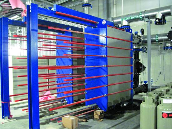
Typical plate heat exchangers used in free cooling.
Free cooling is seasonally limited, however, so chillers are still required to provide year-round cooling. The savings make it a strong option in climates where it can operate for thousands of hours per year. Further, every free cooling hour is an hour the chillers don’t run. This can mean significant life extension of the most expensive component in the mechanical room, with long-term savings in both chiller major rebuilds and capital replacement costs.
Free cooling system operators face two major hurdles. The first is the transition from chiller cooling mode to free cooling, and the change back to chillers when the free cooling operation has ended. This will be covered in some detail, as it is the largest issue in many cases.
The second issue is maintaining system performance over time. While not as immediately critical as the start and stop transitions, it is vital to maximizing the free cooling investment payback. This and other maintenance aspects will also be reviewed.
Conventional Free Cooling Start and Stop Operations
In commercial applications such as office buildings and hotels, the free cooling transition is historically a stop-start process. Water-cooled chillers can struggle to maintain stable operation with the cold condenser water temperatures required for free cooling; as such, the free cooling transition has the chillers shut down (while continuing to circulate chilled water through the building), followed by the adjustment of the cooling tower setpoint to the required free cooling temperature.
![]()
The temperatures and key events in a typical transition to free cooling operation.
The sequence of the chiller shutdown and the cooling tower water temperature drop can total as much as 10 to 15 minutes. This can cause a significant water temperature spike, but fortunately, it may go mostly unnoticed in a commercial facility. Of course, the reverse process happens when exiting free cooling, as the cooling tower water typically has to warm up before the chillers can be started. This is most commonly true with centrifugal compressor chillers, as some rotary screw compressor chillers and other positive displacement designs are more capable of starting with cold condenser water. Practically, however, the largest chillers with the most sensitive loads are centrifugal, so restarting is a significant issue in many cases.
The Importance of Free Cooling Transitions
Like many industrial processes, free cooling systems work well once they are on and running; starting and stopping are the critical times with the greatest upset potential. However, unlike general plant processes, where individual lines or departments would start or stop at any given time, the cooling system supports the entire plant. Upsets there affect the whole operation with greater impacts from failure, especially when the rest of the plant is in full-on normal operations, as would often occur with free cooling transitions.
Consequently, the temperature spike typical in commercial settings is unacceptable in process cooling, particularly in continuous output production such as sheet and film extrusion or parts blow-molding or injection molding. While producing a block of off-spec products is bad, the worst case is the separation of a continuous web process that could require re-threading of the line and possibly even extinguishing modest fires from material drop-outs in reheat ovens.
As a result, many plants with free cooling significantly limit use to times when the transition can be made with full operator awareness and the system can operate for many days or even weeks without having to go back to the chillers. This captures some savings while minimizing the potential production impact of the transitions, but with a significant reduction in the potential benefits. Sadly, it’s not uncommon to see free cooling systems out of service because they had too many upsets and plant management said, “Never again.”
Streamlining Free Cooling Transitions
Given the conditions described, the critical challenge is making the transitions between chiller and free cooling modes as transparent as possible. Smooth transitions enable high operating hours and high year-round load facilities to use free cooling as many hours as possible, including many shorter periods of a day or two, or even a block of overnight hours typical in the fall and spring (i.e., the beginning and end of the free cooling season). Further, the ability to run well in these conditions makes free cooling possible in locations where there are not months of continuous cold, but there are still many hours of potential application.
The keys to acceptable transitions are two closely related items:
- Improving the chiller’s ability to operate longer into the transition to free cooling and start and load sooner in the transition back to chiller cooling, and
-
Minimizing the impact of starting and stopping the free cooling loop (this is not as much of an issue when going out of free cooling, but it still must be done with care).
Understanding Free Cooling Transitions
For successful free cooling start and stop operations, it is necessary to fully understand the process taking place. The starting transition consists of several steps:
- Stopping the chiller(s)
- Lowering the tower water temperature to that required for the heat exchanger to deliver the needed chilled water temperature (e.g., from 75°-48°F/24°-9°C)
- Opening and purging the heat exchanger and its associated piping loops
In most conventional systems, stopping the chiller(s) is the first step. Depending on the chiller type, it may take several minutes to unload and perform a complete shutdown.
The controls then lower the cooling tower water temperature, a 5-15 minutes process depending on (1) the initial water temperature compared to the outdoor conditions, (2) the cooling tower capacity compared to the load (less actual load compared to rated capacity results in faster drops, but plants usually have air compressors and other loads continuing when the chillers are off) and (3) the system volume of water such as tank systems or long runs of large pipe with larger total water volumes.
Opening and purging the heat exchanger is not a long part of the process, but it will add a slug of warm water to the chilled loop when fully opened promptly, as is typical with pneumatic actuated valves. In most systems, this step will add another 1-2 minute delay.
Depending on the system, these steps can result in a total uncontrolled period of 15-20 minutes or more for the total transition, with chilled water temperature rises of up to 20°F (11°C) or more, followed by a pull-down period for the chilled water temperature to stabilize at acceptable levels. If you have ever stood in a mechanical room and watched as the chilled water temperature goes up, 15 minutes is an eternity, and 20 minutes or longer is inconceivable.
Note that when this process is used in commercial applications, the time lag effect is reduced as the system loads are lower compared to peak season design capacity and there are no other cooling tower loads extending the pull-down time. It’s still not ideal, but not as consequential, either.
Several techniques can be employed to dramatically reduce the temperature swing and also maximize the potential free cooling operation and savings. First is enabling the chillers to run better with cold condenser water. This improves operation during the transitions. Next is better management of the heat exchanger start-up, which reduces the transitional temperature swing. The final component is defining the right conditions for entering and leaving free cooling, minimizing the risk of incomplete transitions into free cooling or fault conditions during free cooling operation, while simultaneously maximizing the run time.
![]()
The temperatures and key events in an improved free cooling transition.
Improving Chiller Stability in Free Cooling Conditions
Many chiller designs rely on the pressure difference between the evaporator and the condenser for stable compressor operation (particularly with centrifugal machines) and for oil management and other functions. VFD-equipped centrifugal chillers are more stable with cold condenser water, but even these can struggle in start-ups and with high loads and low delta Ps between the two vessels.
The condenser cooling effect is most directly controlled by reducing cooling tower water flow through several potential means:
- Pump speed control or modulating pump discharge valves
- Chiller valve modulation to either throttle the flow or partially bypass the condenser via control from the chiller (internal to the chiller)
- Chiller valve modulation to throttle or bypass flow through action from the cooling system controls (external to the chiller)
Flow modulation using internal chiller controls is the preferred method. This typically uses a head pressure-based control and ensures the flow control functions even if the system controls are off. In contrast, slowing the cooling tower flow at the pumps may starve other cooling tower water cooling uses, such as air compressors and machine hydraulics.
Unless there is an overriding reason, simple flow modulation to the chiller is the recommended approach. A bypass typically requires additional piping and further requires pumping at a higher rate than is otherwise needed, wasting energy. Only if a consistent total flow was needed for some reason separate from the chiller operation would it be advisable to use a bypass.
Properly implemented, chiller head pressure control can make a chiller capable of running for moderate periods with significantly colder cooling tower water than normally possible. Even so, it’s still not recommended to run chillers for an extended time in parallel with free cooling for at least two reasons, one practical and one economic.
First, the butterfly valves typically used are substantially non-linear. Combined with the control function hysteresis, the condenser flow and resulting head pressure can vary more than desired for continuous operation, even if adequate for a short transition. Under various load conditions (low load, cycling), the instability could cause the chiller to fault, with the potential for insufficient plant cooling.
Second, extended cold condenser operation presumes free cooling also continues. Otherwise, it would be a standard on or off transition. In this case, the system should simply be entirely in free cooling; there is no reason to incur the energy penalty for the chiller operation. If a heat exchanger can’t carry the entire plant load, the usual least cost option is to add more plates. This should be less than a two-year simple payback in most situations.
Managing the Temperature Change and Heat Exchanger Start-up
Enabling the chiller to run deeper into the free cooling transition and start sooner coming out is only the first aspect of reducing the transition impact. The complement to this is more intelligently controlling the heat exchanger flows to minimize water temperature swings. This is performed using modulating control valves on both the cooling tower and chilled water sides, which enables the cooling system controls to have different flows on the two sides through the transition.
For the cooling tower water side, the modulating valve is partially opened as the tower water temperature begins to go down. Opening the valve 20-30% provides additional cooling tower water flow and precools the heat exchanger; the chilled water temperature is unaffected, as that side remains closed. As the cooling tower water temperature drops, the tower side valve opens further until it is open (“open” may not be 100% open, depending on the need to provide pressure and flow to other applications).
The chilled water valve is also opened gradually, but not until the cooling tower side is nearly at the free cooling temperature, generally within a few degrees. When this trigger is reached, the chilled water valve opens partially to purge the warm water slug slowly. The still-running chiller dampens the process temperature rise, and this is assisted further by the cooling tower side pre-cooling. Once the cooling tower water reaches the target temperature, the chilled water valve opens fully, and the chillers are shut down.
There is an unavoidable bump in the chilled water temperature through this transition as uncooled evaporator water flows for several minutes during the chiller shutdown, but this is moderated by the fully operating free cooling. Multiple chillers can be shut down in sequence to further minimize the temperature impact.
When switching back to chiller cooling, the reverse process is followed, although with some adjustment of the valve open conditions depending on the chiller start-up times and temperature rise rate on the cooling tower side.
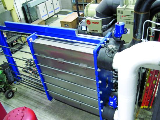
A 1600 ton free cooling heat exchanger with separate modulating control valves on cooling tower water and chilled water connections.
Free Cooling Start and Stop Triggers
The preceding improvements position the system for successful operation with minimal temperature variation and chiller upset risk, but the necessary adjunct is making timely decisions on when to go into and come out of free cooling. Obviously, starting the transition when the wet bulb is too high could cause an extended pull-down time (or even failure to reach the set transition temperatures) and potential issues with the chillers, even with the head pressure controls.
As outdoor conditions generally cycle each day between highs and lows, we can assume when the temperatures are trending down there will be some hours at or below the current reading. A tested strategy for entering free cooling is to delay the start until the wet bulb is below the transition setpoint for long enough to ensure it’s continuous, for example, 2°F (1°C) or more below for at least 20 minutes.
Starting free cooling in these conditions should provide at least several hours of operation, although with the loss of possibly an hour or two on the theoretical start. Given the need to minimize the upset risk, this is an acceptable trade-off, especially if it allows system controls to automatically make the transitions. Despite the start time lag, this would cumulatively provide many more free cooling hours than manually switching the system only during forecast cold spells.
Switching out of free cooling is best done based on the actual chilled water temperature, with thresholds and time delays set for both load-based and equipment failure scenarios. The load-based trigger would be a smaller temperature rise for a longer time (say 2°-3°F/1°-2°C for 10 minutes) while the equipment failure (e.g., “something broke”) trigger would be a higher rise for a shorter time, perhaps 8°-10°F (4°-6°C) for two minutes. These settings must be calibrated so starting a line doesn’t trip the system while still providing prompt recovery if a cooling tower fan fails.
Tuning the Transition Control
Unsurprisingly, the temperature settings and overlap times are significantly variable between systems. Small footprint systems designed for free cooling (i.e., with good cold condition cooling tower performance) may have shorter transitions due to less water volume and plenty of cooling tower effect. Larger systems and those with tanks may have longer transitions, as may conventionally selected cooling towers or cases where the cooling towers are some distance from the mechanical room.
Chiller start and stop operations are also critical. Different chiller types can have different functional step times, as well as different loading rates. It may be beneficial to choose one chiller or type as the lag chiller when going into free cooling and another for coming out. It is highly recommended to work with factory technical services to safely adjust some of the chiller default timers to make the machines more responsive for free cooling operation.
It cannot be overstated how important the careful tuning of the free cooling system and controls is to successful operation. When correctly implemented, the system can operate hundreds of hours or more than might otherwise be the case. Perhaps more critically, it may enable a system to be run at all when it may have otherwise been shut off permanently due to process disruptions.
Freeze Protection for Free Cooling Systems
Given that free cooling requires cold outdoor conditions to operate, managing systems in extremely cold weather is a common question. Different types of cooling towers (crossflow, counterflow) are prone to different freeze patterns, and the free cooling operating temperature can affect the likelihood of freezing (a 60°F/16°C system is less likely to freeze than a 42°F/6°C operation). In addition, the heat load is a major factor; a lightly loaded system is more likely to freeze.
Several approaches can be used for freeze protection. One is to simply manually switch to chiller cooling in extremely cold weather, as the warmer condenser water is less likely to freeze. Another method has the system controls switch to chiller cooling for some period (30 minutes, an hour) to thaw the cooling towers if the fans run at 60 Hz continuously while the wet bulb is sufficiently low that full fan speed shouldn’t be required. Some fans can be stopped or reversed, but that normally requires a multi-cell system to keep control of the chilled water temperature.
As with the system tuning, the best freeze protection approach will be highly dependent on the specifics of each system and location. For system planning purposes, the key point is to be aware of the potential need and select, implement and tune the freeze protection once installed.
System Maintenance for Free Cooling Systems
Given that free cooling is virtually always an addition to an existing cooling system, incremental maintenance requirements are modest. This assumes the cooling towers and pumps are already on adequate monitoring and maintenance, chemical treatment and other supporting programs.
The primary maintenance requirement is periodic cleaning of the heat exchanger. The time between cleanings is highly dependent on the water conditions, cooling tower dirt loading (including particle nature and size), system filtration and hours of operation. The time between cleanings is learned, with observation of the temperatures and pressure drops compared to flows being key indicators.
It is highly recommended the cooling tower water, in particular, is filtered before the heat exchanger to prevent passage blockage and restricted flow. Ideally, an appropriate duplex strainer is used with basket openings less than 50% of the plate spacing; for example, a 0.1-inch plate spacing would suggest an 18 or higher strainer mesh.
Other system maintenance steps include operating the modulating and isolation valves, testing and purging pressure gauge ports (particularly on the cooling tower water, as these are prone to plugging) and checking the condition of flexible connectors and pressure tubing for physical damage or decay over time.
Conclusion
Free cooling systems are a highly efficient means of providing process cooling, however they must be operated and maintained so their operation doesn’t negatively impact their host plant. The critical phase is the transition between chiller cooling and free cooling, and then back to chiller cooling. This article presented extensive information on improving the performance of these transitions. Further, free cooling systems must be maintained and protected from freezing in cold conditions. When all these pieces are in place, free cooling provides highly efficient cooling and extends the life of the chillers, a significant additional benefit of the system.
About the Author

Clayton Penhallegon, Jr. is Managing Member of Integrated Services Group. He has worked for over 35 years with various industries, including plastics, paper, wood products, metal containers and textiles. He holds a Bachelor of Mechanical Engineering from Georgia Tech and an MBA from Georgia State University, and is a registered PE in Georgia.
About Integrated Services Group
Integrated Services Group performs industrial cooling water system operational effectiveness and cost reduction technical services, including system assessments, new and upgrade system design, system start-up and retro-commissioning and high efficiency control design and implementation. ISG celebrated its 25th anniversary in 2022 and serves clients throughout North America. For more information, visit https://www.isg-energy.com.
For similar articles on Cooling Controls System Assessments, please visit https://coolingbestpractices.com/system-assessments/cooling-controls.
Visit our Webinar Archives to listen to expert presentations on Cooling Controls System Assessments at https://coolingbestpractices.com/magazine/webinars.