Comparing Air-Cooled and Evaporative Systems to Optimize Efficiency, Reduce Water Use, and Manage Industrial Cooling Costs
03/25/2026
There are several methods of fluid cooling available for industrial applications. Among them are evaporative fluid cooling (using the evaporation of water), dry fluid cooling (using airflow to cool a fluid stream), and hybrid cooling (a combination of evaporative and dry cooling, in which some water is evaporated during the cooling process). With data center development, dry fluid cooling has recently gained more attention as certain jurisdictions seek to reduce the overall water use by facilities in their area. This article will be a high-level overview of the water-saving capabilities of dry fluid cooling technologies in contrast to more traditional evaporative cooling technologies.
Since dry fluid coolers are less common than evaporative coolers, we should define what we mean by dry fluid cooling. Dry fluid cooling (or dry cooling, for short) is a type of fluid cooling removing heat from a system using ambient air for heat rejection. This is also known as sensible heat transfer. Because evaporative cooling is not taking place, there is no latent heat rejected from the system. While this means dry cooling cannot take advantage of this latent heat transfer (estimated at roughly 85% of the heat transfer present in evaporative systems), it also means no water is consumed or evaporated during the heat rejection process. Some dry coolers (also referred to as towers in certain cases) can operate in two different modes: wet (where some water is evaporated to improve performance) and dry (no water is evaporated) or a combination of the two. These towers would be classified as hybrid or adiabatic depending on the complement of technologies used in the wet mode. For the purposes of this article, we will focus on dry cooling only, but some of the principles discussed will apply to the dry mode operation of other units capable of sensible heat rejection. For those familiar with automotive radiators, the working principle is much the same as a dry cooler, at least when it’s not raining out!
The Two Main Dry Cooling Configurations
Dry coolers come in several basic configurations. The two main configurations are flat (also called “table coolers”) and V-bank (coils oriented in a vertical V shape). Figures 1 and 2 depict examples of these configurations. The flat cooler has hot fluid entering the unit on the right with cooled fluid exiting to the left; air is pulled across the fluid coil, picking up heat and exiting through the top. The V-bank configuration is similar, but flows from top to bottom. The air flow in the V-bank is also drawn across the coil, but it is drawn from outside in and up rather than from bottom to top, as seen in the flat configuration. In both examples, no water is used during the rejection of heat; only sensible rejection to the atmosphere. The main advantage of the V-bank configuration vs. the flat configuration is operators can get more heat transfer surface with ambient than with a flat configuration for the same footprint. This is because the coils in the V-bank are oriented in a more vertical arrangement than the flat cooler. V-bank coolers tend to be more expensive, but this can vary depending on manufacturer or application.
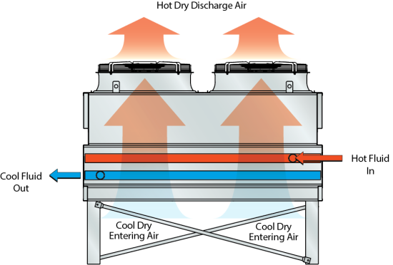
Figure 1: Flat configuration dry cooler (Image courtesy of EVAPCO)
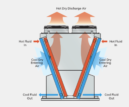
Figure 2: V-Bank configuration dry cooler (Image courtesy of EVAPCO).
Cooling System Definitions
Before we get into examples illustrating the differences between equivalent capacity dry and evaporative cooling systems, we should define a few terms relevant to the discussion. These terms are used for both dry and evaporative systems, but are defined in slightly different ways for both. Figure 3 shows a graphical representation of these definitions. Note the figure depicts wet bulb temperature as the basis for the tower approach. This would be dry bulb temperature for dry cooling applications and wet bulb temperature for evaporative applications.
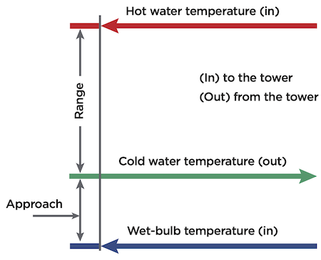
Figure 3: Approach and range definitions (note wet-bulb temperature is dry-bulb temperature in dry cooling)
Approach: The difference in temperature between cooled fluid and entering air dry bulb temperature (for evaporative cooling, this would be air wet bulb temperature). The typical approach for a dry cooling application is 10-18°F (6-10°C), contrasted with 7-12°F (4-7°C) for evaporative applications. Approach can go down as low as 5°F (3°C) with certain types of equipment in certain types of applications.
Range: The difference in temperature between entering and exiting fluid. The typical range for a dry cooling application is 9-15°F (5-8°C); similarly, 10-15°F (6-8°C) is common for evaporative applications.
Typical Dry Cooling System Applications
In general, dry cooling can be used any place typical evaporative cooling is also used (with the caveat that the required fluid temperature can be reached, given the installation location). Here are a few areas where dry cooling might be an option, given the previous limitations.
Heating, ventilation and air conditioning (HVAC) is present in nearly every building today to some extent, and a widespread application of fluid cooling in these systems is the chiller/cooling tower combination, especially on larger systems. Water-cooled chillers are connected to cooling towers, and these towers are traditionally evaporative. While this is the standard, dry cooling is also an option for these applications. In this case, the dry cooler can be installed in lieu of or in supplement to a traditional evaporative cooling tower to save on raw water costs, as well as associated water treatment costs and chemicals for evaporative systems. However, simply replacing an evaporative tower with a dry cooler is rarely a recipe for success, as there are limitations on what temperature water can be delivered to the chiller. This is due to the approach for a dry cooler being based on the dry bulb temperature rather than the wet bulb temperature for an evaporative system. Since the dry bulb temperature is always higher, the water delivery temperature will be higher as a consequence. This higher cooling water temperature to the chiller can impact performance, so pay careful attention when matching a dry cooler to a water-cooled chiller.
Refrigeration is another potential application for dry cooling. The majority of condensers in industrial refrigeration use evaporative cooling, but this is not always the case. The same limitations around dry bulb vs. wet bulb temperature in the HVAC example apply to refrigeration applications, but the properties of the refrigerant should be considered directly, as condensing at the dry bulb temperature may not be acceptable depending on system refrigerant properties.
Finally, process cooling is a potential application for dry cooling. Some applications (including the car radiator example stated earlier) include closed-loop processes requiring heat rejection at higher temperatures. Examples in industry include cooling for engine water jackets and oil cooling in power-generating systems, water-cooled air compressors and water-cooled compressed air dryers. All these systems typically operate at higher temperatures than the typical water-cooled chiller, and can be a great application for dry cooling where evaporative cooling is either not currently present or not feasible due to water restrictions or water quality issues. These are just a few examples, but, in general, higher temperature processes can do well with dry cooling due to the large approach temperatures involved.
The Pros and Cons of Dry Cooling
As with everything in life, there are pros and cons to dry cooling. The biggest upside to dry cooling is that it turns the process fluid loop into a closed system (evaporative systems are typically open loops). This means dust, debris and microbiological growth (all associated with evaporative systems) are not a factor for completely dry cooling systems, so no filtration or treatment is required to deal with these issues. This has enormous benefits to maintenance, as water treatment becomes much less of a critical factor in cooling system performance. While the process fluid loop still requires basic water treatment and monitoring, this pales in comparison to the ongoing maintenance and treatment of a typical open loop evaporative system.
Another (obvious) upside of dry cooling is there are no raw water costs associated with its operation. While raw water costs are not typically high in most areas, they can be quite expensive in dry or water-stressed areas of the country. These water savings are in addition to the chemical and maintenance savings mentioned previously.
However, some drawbacks to dry cooling must be taken into account. One we have already alluded to is the exiting fluid temperature is limited by the approach to the ambient dry bulb temperature. This can be mitigated by careful design, but if lower temperatures are critical to the application, dry cooling may not be the best option.
Additionally, the overall heat rejection capacity compared with an equivalent footprint evaporative system is lower. This is due to the latent heat transfer capability available in an evaporative system, whereas the dry cooling system is limited to sensible heat rejection only.
Dry cooling is associated with higher power consumption than an equivalent capacity evaporative system. Heat transfer between the cooler and the ambient atmosphere is primarily driven by fans moving air across the cooler, and these fans consume a lot of power to move the required amount of air. Evaporative cooling systems also use fans, but these are typically lower horsepower and less critical to the process than in dry cooling.
Finally, dry cooling tends to have a higher capital installed cost than an equivalent capacity evaporative system. This is usually due to the cost of materials and labor to assemble the coils, fans, motors and other associated materials present in dry coolers vs. those used by evaporative cooling towers. Greater electrical capacity to drive the additional, larger fans present on dry coolers also increases capital installed cost.
Table 1 summarizes some of the differences between dry cooling and evaporative cooling. Given that evaporative cooling tends to be the standard, the figure shows typical magnitudes for dry cooling vs. an equivalent capacity evaporative cooling system, hence why the Evaporative Cooling column is all 1X. The big benefits of dry cooling are no water consumption and relatively similar operating expenditure, while energy consumption, required footprint and capital expenditure are all higher for dry cooling. Operating expenditure is relatively even between the two because of the tradeoff between water consumption, treatment and maintenance associated with evaporative systems vs. the electrical operating cost for dry cooling.
Table 1: Comparing dry cooling and evaporative cooling.
| Dry Cooling | Evaporative Cooling | |
| Water Consumption | 0X | 1X |
| Energy Consumption | 2X | 1X |
| Footprint Required | 4X | 1X |
| Operating Expenditure | 1X | 1X |
| Capital Expenditure | 4-5X | 1X |
Specifying Dry and Evaporative Cooling Systems: An Example
To show practical differences between a dry cooler and an evaporative type, we’ll go over a sizing example. The basic process for sizing either a dry cooler or evaporative cooling tower is much the same: verify installation weather data against process fluid temperature requirements, establish the required heat transfer rate and select a cooler to match.
In our example, we will look at an installation location with peak weather conditions, indicating a 95°F (35°C) dry bulb temperature and an 80°F (27°C) wet bulb temperature. The heat rejection required by the process is 100 tons (1,200,000 BTU/hr). The approach in both instances will be 10°F (6°C), and the range will be 10°F (6°C). Since the range in both cases is 10°F (6°C), that means the delta across the cooler is also 10°F (6°C), and we can determine the flow rate required is 240 gpm (Q = 500*dT*Flow). The only variable in this example is the dry bulb vs. wet bulb temperature (95°F/35°C vs. 80°F/27°C).
Using our definitions of approach and range, we can determine the outlet and inlet temperatures of the coolers and see how dry vs. wet operation affects them.
For the dry cooler, the approach (A) can be used to find the outlet temperature (OT) using the dry bulb temperature (DBT).
OT= (DBT + A) = (95 + 10) = 105°F
The inlet temperature (IT) can be found by using the OT and the range (R):
IT= (OT + R) = (105 + 10) = 115°F
The same procedure can be used for the evaporative cooling tower, with the main difference being the wet bulb temperature (WBT) is used in place of the DBT. Outlet/inlet temperatures for the evaporative cooler are as shown here.
OT= (WBT + A) = (80 + 10) = 90°F
IT= (OT + R) = (90 + 10) = 100°F
If we use these parameters and use EVAPCO’s catalogs to select both a dry and evaporative cooler matching these criteria, we find an EAW-VD15S2ZB (dry cooler) and an AT 14-2G6 (evaporative cooling tower) meet the requirements. Their approximate dimensions (L x W x H) are 11’ 10” x 7’ 3” x 9’ 7” and 6’ x 4’ 1” x 9’ 7” respectively, indicating the evaporative unit is smaller overall than the equivalent dry cooler (roughly 86 sq ft required for the dry cooler vs. 24.5 sq ft for the evaporative cooling tower). This works out to a 3.5X footprint requirement, which tracks with our earlier estimation of a 4X impact. Figures 4 and 5 depict the selected dry and evaporative coolers, and Table 2 shows a comparison summary between the two. The dry cooler has two fans, whereas the evaporative cooling tower has only one, which is in line with the previously discussed increased electrical and capital cost requirements of dry cooling.
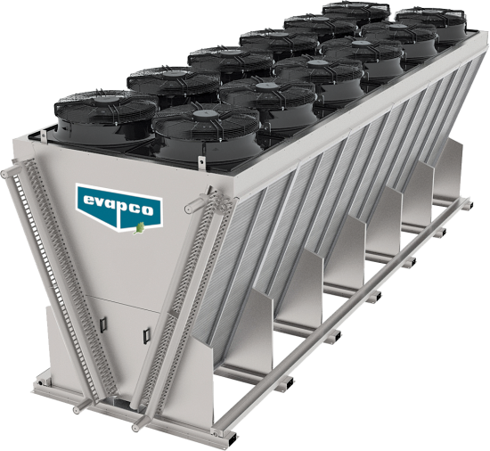
Figure 4: EAW-VD15S2ZB dry cooler (Image courtesy of EVAPCO).
.png)
Figure 5: Representative image of an EVAPCO AT Series cooling tower; actual model not shown (image courtesy of EVAPCO).
Table 2: A comparison between two specified cooling systems
| Dry Cooling | Evaporative Cooling | |
| Dry/Wet Bulb Temperature (°F) | 95 | 80 |
| Heat Rejection (tons) | 100 | 100 |
| Approach (°F) | 10 | 10 |
| Range (°F) | 10 | 10 |
| Outlet Temperature (°F) | 105 | 90 |
| Inlet Temperature (°F) | 115 | 100 |
| Required Flow Rate (gal/min, water) | 240 | 240 |
| Equipment Selection | EAW-VD15S2ZB | AT 14-2G6 |
| Approximate Dimensions (L x W x H) | 11' 10" x 7' 3" x 9' 7" | 6' x 4' 1" x 9' 7" |
In this example, we’ve deliberately controlled for all variables (load, approach, range and flow rate) with the exception of the ambient temperatures involved to illustrate the main difference due to dry vs. evaporative cooling. The dry cooler cannot produce water as cool as the evaporative system, but this may not be an issue depending on the system being served. Additionally, the dry cooler must be larger to serve the same heat rejection load. However, the estimated peak evaporation rate for the evaporative cooler at a 10°F (6°C) delta and 240 gpm of flow is around 2.4 gpm (1% of circulating flow), so this should be taken into account. This evaporation rate varies depending on system delta, flow rate and time of year, but this is a fair estimate at peak. The dry cooler avoids this raw water and associated treatment cost.
In summary, dry cooling can be a great way to eliminate one of the largest water points-of-use in an industrial setting, and can be applied in a variety of applications. Matching process suitability is a key factor in implementation success and should not be underestimated. In addition, system performance should be evaluated across an entire operational year to understand the full impact of using a dry cooling system vs. an evaporative cooling system, as dry cooling may be lower cost in off-peak months (the installation location will affect this heavily). Finally, hybrid or adiabatic coolers can give the best of both worlds, using some water at peak loading and operating in dry modes the rest of the year. Again, evaluation across an entire year’s worth of weather data is helpful in matching needs with equipment. For more on adiabatic cooling, read “Adiabatic Coolers: An Evolution in Sustainable Process Cooling,” Compressed Air Best Practices, March, 2026.
About the Author

Nick McCall, PE, is a Senior Project Engineer for E4E Solutions. He has a B.S. in Mechanical Engineering from the Georgia Institute of Technology. He has 16 years of experience as a mechanical engineer performing design for clients in the food and beverage, power generation and general manufacturing sectors. Project experience includes design and build installation, construction management and start-up and commissioning of new utility, process and packaging lines. His areas of expertise include designing and engineering process, utility and power generation designs, engineering bid packages, utility specifications and commissioning utility systems.
About E4E Solutions
E4E Solutions is an EPC (engineer, procure, construct) supplier specializing in the development, design engineering, implementation and financing of innovative solutions meeting decarbonization goals, reducing operating costs and modernizing and renewing utility system infrastructure. It has a successful track record developing high ROI, sustainable, cost-saving projects for industrial, manufacturing and large commercial clients around North America. For more, visit https://e4esolutions.com.
To read articles about Dry Coolers, visit https://coolingbestpractices.com/technology/dry-coolers.
Visit our Webinar Archives to listen to expert presentations on Dry Coolers at https://coolingbestpractices.com/magazine/webinars.