
Closed-Loop Fluid Cooler Design Eliminates Potable Water Use While Improving Engine Cooling Reliability
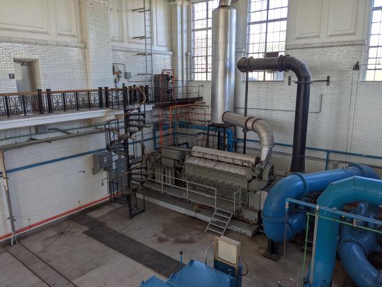
A pump station for a Midwest water production utility uses two large diesel engines to power critical operations. One of the engines drives a large high-lift pump to boost pressure in the distribution system during extreme hot weather periods when there’s an increased demand for water in the community. The other engine is part of an emergency generator package backing up the pump station during power outages. It’s also used for curtailment when called upon by the electric utility.
Both engines are located inside the pump station building and use finished water (water treated and prepared for domestic, potable use) for cooling in a once-through configuration: Warm water from the engine heat exchangers is discharged to a drain and eventually reprocessed at the water treatment plant. The water utility engaged IMEG to assist in developing options for both engines to reduce cooling water use and help avoid potential environmental risks associated with the current method.
The high-lift pump engine is rated at 1,864 kW (2,500 horsepower [hp]) and was installed around 1960. The engine produces nearly 4,000,000 BTUH of heat at full load and requires approximately 220 gpm of cooling water during operation. The generator engine, installed around 1990, has a 12-cylinder block and is rated at 3,810 kW (5,105 hp). The engine produces about 6,450,000 BTUH of heat at full load and uses about 425 gpm of cooling water during operation. Combined, the engines use approximately 1,000,000 gallons of potable water each year for cooling purposes. The temperature of the finished water was approximately 55°F (13°C). The implementation of the closed loop cooling system described here eliminates the need for nearly 1,000,000 gallons of water per year to cool the engine systems.
The Engineering Design Process and System Selection
The original pump station building was constructed in the 1920s. The owner had copies of some of the original design drawings, but it was clear changes had been made over the years. The design team used a 3D scanner to capture features of the existing building and site around the pump station. The point clouds generated by scanning were used to develop a 3D model of the existing structure and utility systems for design coordination purposes.
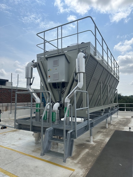
As part of the design process, the design team evaluated several different options for engine cooling. Open cooling towers were briefly considered but quickly discarded. The presence of many cottonwood trees, potential wintertime operation, water use due to evaporation and blowdown, large footprint and weight, redundancy (or lack thereof), chemical treatment and maintenance requirements were all deterrents. While these systems would work, they would be a maintenance challenge to the staff and consume water through evaporation cooling, which we were trying to limit. Chillers, either water-cooled or air-cooled, would be relatively expensive to purchase and require substantial electrical infrastructure. The engine cooling systems are typically cooled with warmer water, which would not require a refrigerant compressor cooling system like a chiller. Radiators and fluid coolers with closed water loops appeared to be more viable options but would require glycol for freeze protection and piping system corrosion prevention. Both types of equipment could be selected with multiple fans, which would provide some level of redundancy; however, radiators would require a large footprint, which was at a premium at this site as explained in more detail in the later sections. Based on all of this analysis, a dry fluid cooler option was selected for further design analysis as it fit the project needs and requirements the best. Energy efficiency was considered but ultimately did not drive the decision for the selected system. The main decision points were maintenance, footprint, cost, redundancy and saving water.
Selections from two different fluid cooler manufacturers were requested for comparison. Criteria such as ability to turn down, quantity of fans, fluid pressure drop, materials of construction, footprint, height, weight, electrical power, cost, lead time and local representation were considered and evaluated. A spare fan, motor and controller were ordered with the final equipment selection for the owner to have on hand in case of an emergency.
Having a large quantity of fans was important as they provide a better level of turndown for when ambient temperatures aren’t at peak design temperatures and redundancy if a fan were to fail. Due to the nature of our engine systems, our closed loop system needed to be flexible and adaptable to the heat load on the system from the engines. Having these options available at the fluid cooler equipment ensured our system would be able to adapt to changes in the environment.
Fluid pressure drop was also an important item to evaluate. Due to fluid coolers not having refrigerant compressors, the main way to save energy is by reducing pumping losses through the heat exchanger. Higher pressure drop likely means a smaller footprint and smaller tubes, but eats up pump energy and requires a higher electrical load on the system.
Fluid Cooler Sizing and Location
Both fluid cooler systems were sized to operate at up to 105°F (41°C) ambient temperature, based on ASHRAE design conditions for the location and because the equipment would inherently be required to operate when the outdoor temperature is the hottest. The generator engine cooling loop was designed for 427 gpm, taking warm water from the engine heat circuit at 157°F (69°C) and pushing through the fluid cooler heat exchanger for a return/discharge water temperature of 122°F (50°C) – a 17°F (9°C) approach above ambient. The existing internal engine heat exchanger was bypassed (more about this later), and the cooling water was circulated directly through the entire engine circuit. The original connections to the potable water system were left in place (with lockable valves) as a backup option should the fluid cooler ever need maintenance when the generator was called to operate. The fluid cooler for the high-lift pump engine was designed with a new heat exchanger, creating independent loops for the engine-side and the fluid cooler-side. The fluid cooler loop was designed to provide 330 gpm of 120°F (49°C) cooling water to the heat exchanger and return 148°F (64°C) to the cooler. On the engine-side of the heat exchanger, 450 gpm of water was circulated with supply and return temperatures of 155°F and 175°F (68°C and 79°C), respectively.
Cooling Water Pumps Selection and Location
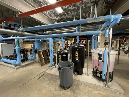
The next step was selecting circulation pumps for the closed loops. Redundancy was desired; therefore, each system would require at least two pumps. Both independent pumps and pre-packaged pump skids were considered. Although a higher initial equipment cost, the packaged skid option resulted in a smaller footprint and simplified the installation of piping and controls. The final pump skid selection included three individual pumps with variable-frequency drives (VFDs), each sized for 50% of the required capacity. The onboard controller for the pump skids is capable of operating based on constant system differential pressure or flow rate, and can lead/lag/alternate pumps to equalize run time. It also calculates the most energy-efficient operation and adjusts individual pump speed on-the-fly.
Pump skids for both systems, along with air separators, expansion tanks and glycol fill stations, were placed in a basement area of the pump station building. Each of these systems was selected based on the fluid parameters, temperatures and volume we were using in each system.
Fluid Cooler Piping and Controls
Piping for the fluid cooler systems was sized to limit pressure drop and conserve pumping energy: 4-inch steel piping was used for the high-lift pump engine, and 6-inch for the generator. The pipes were sized based on velocity, pressure drop and routing space availability. The piping for both systems was sized around 4.5-5.5 ft/s at their respective flow rates. Glycol also had to be accounted for, as it directly affects the density of the fluid. As described later on, the diesel pump system required the addition of a separate heat exchanger and required us to increase the flow rate to 330 gpm to reject heat adequately. This flow rate was determined on site by increasing the speed of the pumps and evaluating the flow capacity the pumps had with the current pipe routing, in order to provide the maximum amount of flow available for the new heat exchanger.
The fluid coolers and pump skids were supplied with factory controls. Flow meters and temperature and pressure sensors installed in the piping network provided signals to equipment controllers to modulate fluid cooler fans and pumps in order to maintain the needed loop water temperatures for each engine. Both engines have thermostatic valves with onboard controls modulating to a setpoint for the entering water temperature to the engine. This will reduce the load on fluid coolers when peak demand isn’t required. Basic information and alarms from the fluid cooler systems were linked to the existing SCADA control system for the pump station so operators could monitor and react to any issues.
Lessons Learned by the Engineering Team
In this story’s introduction, we noted both diesel engines are relatively old, especially the high-lift pump engine. Therefore, knowledge of the existing systems and documentation from manufacturers and representatives was minimal and difficult to attain. Initially, it was assumed the existing high-lift pump engine-side shell-and-tube heat exchanger was adequate to remain, and engine water temperatures and flow rates were estimated for design. During initial system startup and commissioning, however, the engine water loop could not reject heat quickly enough, and the engine had to be shut down before it overheated. It was later determined the engine-side heat exchanger no longer had enough capacity due to the warmer water temperatures delivered from the fluid cooler (compared to potable water). Therefore, a new plate-and-frame heat exchanger was selected, ordered and installed. The original heat exchanger was removed. The next iteration of startup and commissioning proved to be successful.
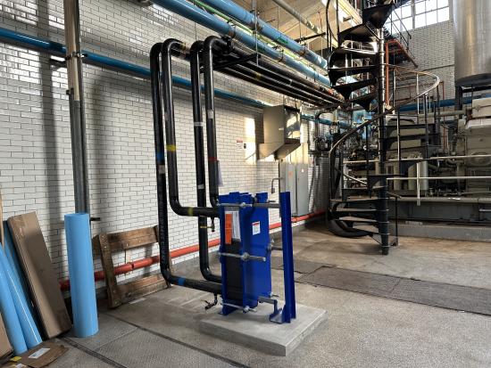
For the generator engine, the original integral heat exchanger proved to be undersized with the different water temperatures, as well. To remedy the issue, IMEG worked with the local generator factory representative to develop a solution bypassing the heat exchanger and allowing fluid cooler water to flow directly through the engine circuit. In doing so, the glycol fluid had to be changed to meet the manufacturer's requirements, and additional system expansion volume was added. A second, separate glycol feed station had to be installed for the generator system.
Through the course of construction, the decision was made to install change-over piping for both engines to allow connection back to the finished water in case either fluid cooler was disabled. Since the pump station was considered critical infrastructure, this flexibility put operators and stakeholders at ease.
Water Savings
The main driver for this project was reducing water usage for the two engine cooling systems. With the existing operation consuming nearly 1,000,000 gallons of water per year, IMEG had to evaluate which systems would adequately cool the engines without using as much water.
The water utility provided IMEG with estimated operating hours per year for each of these systems. This data showed the high-lift pump operated for two to four hours every month, as well as during emergencies. At 220 gpm of flow, this totaled 26,400-52,800 gallons per month, or 316,800–633,600 gallons per year to cool one engine. The data also showed the generator engine operated for approximately 12 hours per year, although this could be higher depending on emergencies. At 425 gpm, this was approximately 306,000 gallons per year.
The closed loop cooling system was selected because it didn’t require a constant supply of water. Once the system is filled, no additional water is required during operation. Water is heated by the engine, then cooled by the fluid cooler before going back through the system. The closed loop cooling system uses glycol to provide freeze protection and chemical treatment, but reduces the requirement for a large amount of water, saving 1,000,000 gallons of potable water per year.
Conclusion
Adding closed-loop cooling water systems to existing industrial equipment can reduce water use, minimize potential environmental risks and provide more reliable operation. However, careful research and planning are required to ensure correct system design, avoid installation delays and minimize system outages and disruption to services or products provided by the operation.
About the Authors
 |
 |
Grant Nook, PE. |
Luke Streit, PE. |
Grant Nook, PE, is a Mechanical Engineer at IMEG. He is experienced in the evaluation, analysis and design of mechanical systems, including heating, ventilating and air conditioning (HVAC), chilled and hot water distribution, piping and fire protection systems.
Luke Streit, PE, is a Project Executive and Lead Mechanical Engineer at IMEG. An experienced industrial process engineer, he has designed and managed projects for a diverse range of commercial and industrial facilities, focusing on specialized mechanical and process equipment systems.
About IMEG
IMEG is an engineering design firm with more than 100 offices and 3,100 team members, combining the comprehensive expertise of a national leader with the personal connections of a local firm. Ranked among the top engineering firms in the U.S. (#4 on BD+C’s top Engineering Firms and #48 on ENR’s Top 500 Design Firms), IMEG transforms environments and communities through innovative, high-performance design and infrastructure solutions. For more information, visit https://imegcorp.com.
To read articles about Fluid Coolers, visit https://coolingbestpractices.com/technology/fluid-coolers.
Visit our Webinar Archives to listen to expert presentations on Fluid Coolers at https://coolingbestpractices.com/magazine/webinars.
