Turning Process Heat into Sustainable Facility Heating
06/23/2026
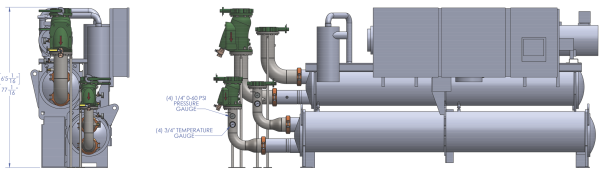
Process Cooling Systems’ rendering of the heat pump chiller installed at Haartz’s facility. Click to enlarge.
At its Acton, MA, plastics extrusion facility, Haartz Corporation launched a major energy initiative designed to reduce natural gas consumption by electrifying a critical heating load. What’s more, the initiative simultaneously recaptured waste heat from process cooling operations. Working with Process Cooling Systems, utility consultant Leidos and National Grid, the company implemented a large-scale water source heat pump system converting process heat into usable heating energy for a high-capacity makeup air unit. The project also reduced load on the plant’s central chilled water infrastructure, lowering cooling demand while supporting broader carbon reduction goals.
The installation represented an unusual convergence of industrial process cooling, heat recovery and HVAC integration. The system combined a water-cooled, rotary screw chiller operating in heat pump mode with a roof-mounted makeup air unit, a custom pump skid and a PLC-based controls package engineered specifically for the application. The project required complex piping integration, structural modifications, coordinated commissioning and extensive control tuning. By early 2026, the system had been commissioned and placed into operation, creating what participants described as one of the first industrial-scale implementations of its kind within their organizations. The system is estimated to save 111 tons of carbon output each year.

Matt Blanchard, Application Engineer, Process Cooling Systems.
Meeting Energy Reduction Goals
The Haartz facility manufactures automotive fabric products involving plastic coating processes. The production lines apply plastic material to fabric webs before cooling and winding the finished material for storage. Large process cooling loads throughout the plant cool production rolls and remove machine heat generated during extrusion operations.
Process Cooling Systems had supported Haartz for over 30 years before the project began. The company previously worked on the facility’s cooling tower and chilled water process systems. This initiative didn’t originate from Haartz, however. Instead, the project emerged through work being conducted by Leidos, an energy modeling and utility incentive consulting company that had been evaluating energy reduction opportunities throughout the facility.
“Leidos and Haartz were working together on a wide array of energy savings projects,” explained Matt Blanchard, Application Engineer, Process Cooling Systems. “Leidos goes into facilities and identifies energy savings projects, things that may qualify for rebate-incentivized offsets and cost offsets. They were working with Haartz on several projects, some unrelated to Process Cooling’s area of expertise. This one came up, and we’d previously worked with Leidos and many other customers across the Northeast, primarily Massachusetts, New Hampshire and Rhode Island.”
Because the plant handled volatile vapors stemming from manufacturing operations, the building required substantial exhaust airflow and continuous makeup air replacement. That heating demand became the target load for electrification.
This project focused on reducing carbon emissions associated with combustion heating. The idea was to capture thermal energy already present within the manufacturing process and redirect it to plant heating loads instead of relying exclusively on natural gas combustion.
“They identified a project as a carbon offset, a gas emissions reduction project, where we would convert process heat to air heat, or heat for makeup air,” Blanchard said. “We’d take that from a production heat source within the facility, pass it through an industrial heat pump and use it to generate heat with an electrical input. In doing so, we were able to transfer waste heat and minimize natural gas consumption.”
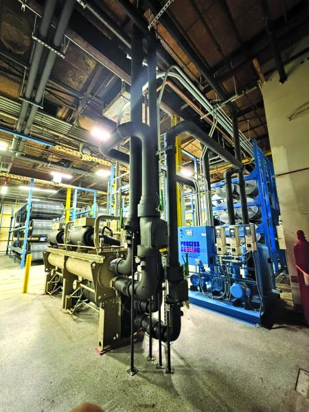
A central heat recovery equipment circulates fluid between the house chilled water system and the recovery system.
Specifying the Best Heat Pump Chiller for the Requirements
The project formally began in late 2024. Initial engineering started in the fall, after Process Cooling Systems received the project award. The engineering scope focused first on defining the heating requirement previously handled by a gas-fired makeup air unit. The company selected both the makeup air equipment and the heat pump chiller based on those operational requirements.
“We knew we were replacing an existing gas-only makeup air unit,” Blanchard said. “We were able to select an air makeup unit and a heat pump chiller providing the same output. We completed final engineering, checking on equipment submittals, honing the sequence of operations for the primary air heating equipment, the chiller and our PLC system.”
The final system centered on a water-cooled rotary screw chiller configured for simultaneous heating and cooling operation. The unit operated as both a chiller and an industrial heat pump. The company selected the system partly because of existing service relationships and support infrastructure.
“We are not a chiller manufacturer. We’re a systems integrator,” Blanchard said. “Part of what we do is working with manufacturers that have the best network of service and support. Trane had equipment fitting the application and a service history we’ve dealt with for many years.”
The makeup air equipment selection followed a similar logic. Haartz already operated an Absolute Air makeup air unit elsewhere in the facility, making the manufacturer familiar to plant personnel. The new makeup air unit was designed for approximately 25,000 cfm of airflow and incorporated a hot water heating coil supplied by the heat pump system. A secondary natural gas burner remained in place primarily as backup heating capacity and for periods when process heat recovery might be unavailable.
The heat pump itself was designed around a 180 ton water-cooled chiller platform capable of generating approximately 2,100 MBH of heating capacity while simultaneously shedding approximately 135 tons of load from the central chilled water plant. The system used R-513A refrigerant.
An exterior piping connection allows the makeup air unit coils to use the recovered energy.
Process Heat Recovery Saves Energy and Natural Gas
The system architecture relied on recovering heat from an existing chilled water return header serving process equipment throughout the facility. The plant already operated a central chilled water system supplying multiple process loads. Rather than creating a separate heat source, the project captured energy already present in the returning process water stream.
“We are drawing off of an existing chilled water return,” Blanchard explained. “We’re pulling off that return assuming we’re having an elevated water temperature. We’re passing it through the evaporator side of a water-cooled chiller, where it is getting cooled and then passed back into the chilled water return downstream of where it’s taken off.”
The system effectively created a tertiary cooling loop connected to the larger chilled water infrastructure. The process return water entered the evaporator side of the heat pump chiller at approximately 54°F (12°C) and returned to the central system at roughly 46°F (8°C). Flow through the process side operated at approximately 230 gpm under design conditions using variable flow control.
As heat was removed from the process water, the refrigerant circuit transferred energy to the condenser side. The condenser loop then generated an approximately 130°F (54°C) glycol solution supplied to the makeup air unit heating coil. The heating loop incorporated both primary and standby pumps mounted on a custom pump skid.
“The byproduct of creating the heat is energy savings off of the main chilled water plant,” Blanchard said.
Because the recovered heat offset natural gas combustion while also reducing cooling demand on the central plant, the installation created simultaneous savings in multiple utility systems. The facility already operated a waterside economizer system associated with its chilled water infrastructure. By reducing load, the project further decreased cooling system energy demand.
Although water conservation was not the primary objective, reduced central plant cooling load also produced secondary water savings associated with reduced cooling tower operation.
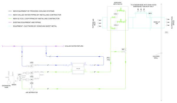
This schematic diagram shows how the heat pump chiller integrates with the plant’s existing systems. Click to enlarge.
Makeup Air Integration and Volatile Vapor Management
The makeup air portion of the project represented a critical operational component. The facility required large volumes of conditioned makeup air because manufacturing operations generated volatile vapors needing to be captured and removed continuously from occupied spaces. The facility used direct exhaust systems to pull vapors downward and away from operators before routing them to thermal oxidization equipment elsewhere in the process.
“This is a plant processing a lot of volatile vapors, so they have to recapture them,” Blanchard explained. “Because of that, to keep their staff safe, they need to draw as much as possible. They have a lot of direct exhaust sucking those vapors down and through the floor, away from their operators.”
The makeup air unit existed to neutralize building pressurization caused by the continuous exhaust demand. The heating load remained constant regardless of whether the need originated from comfort conditioning or process ventilation requirements.
“The project itself was saying, ‘How can we take natural gas combustion and electrify it?’ We’ve got 25,000 cfm we need to heat from, in worst case, -5°F (-21°C) to 65°F (18°C) for the comfort of our employees,” Blanchard said.
The makeup air system was designed so the heat pump became the primary heating source while the gas burner functioned mainly as backup capacity. The installation also incorporated an emergency diversion damper requested by Haartz. That allowed the heat pump chiller to operate as supplemental cooling capacity during summer conditions, if required. In that mode, the system could bypass building heating loads and reject condenser heat outdoors while maximizing chilled water cooling to the process.
Indoor Equipment Installation with Minimal Disruption
Physical installation began in the spring of 2025. The first equipment installed inside the facility included the pump skid and the heat pump chiller. Haartz created space for the equipment by removing portions of existing material storage racks adjacent to production areas. The installation footprint had to remain compact because the area surrounded active manufacturing operations and critical building access points.
“They eliminated basically one-and-a-third racks to fit this in,” Blanchard said. “We were able to keep this as small as possible to have the lowest impact on their existing facility.”
The indoor equipment sat adjacent to production lines while maintaining the required egress clearances for explosion-proof areas within the building. Process piping connected the heat pump skid to the existing chilled water return header serving production equipment throughout the plant. Because the new system tied directly to operating process cooling infrastructure, installation sequencing became critical. The needed production system shutdown was minimal.
“There was one small shutdown for this facility for the main process piping,” Blanchard said. “That was so we could tie off the chilled water returns, but that shutdown lasted only as long as it took to drain the header, make the connections and recharge the header.”
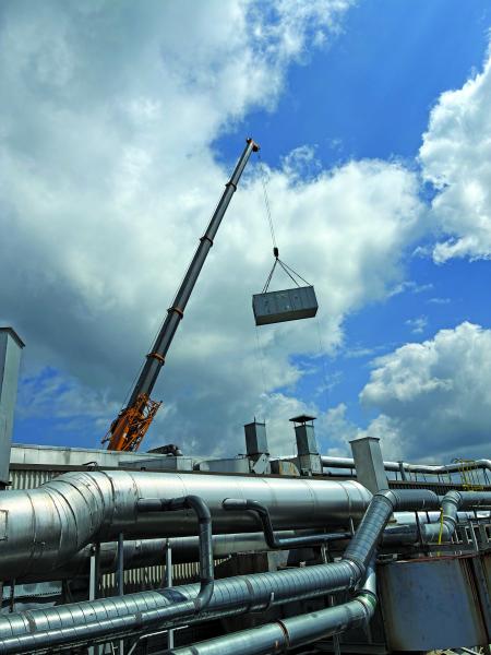
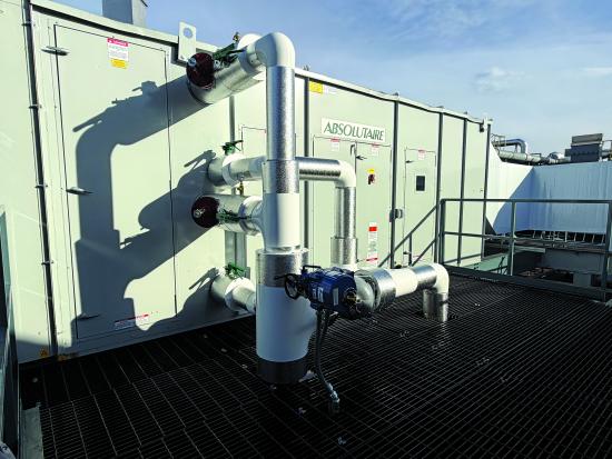
Coordinated rigging and crane work was essential to set and assemble the makeup air unit.
Discovering the Need for Roof Structural Modifications
While indoor equipment installation progressed during spring 2025, additional project requirements emerged regarding rooftop equipment support. The new makeup air unit required roof mounting, which introduced structural engineering challenges not defined in the original project scope. The company coordinated the structural analysis and steel modifications necessary to support the new equipment.
“There were some parts of the scope that were not included in our initial proposal that, over time, needed to be included,” Blanchard explained. “We had to have some structural engineering done on Haartz’s behalf to make sure we could put the outdoor unit where we wanted to.”
Additional spanning beams were installed between existing roof structures to support the new makeup air system. Those modifications occurred during the summer of 2025 before rooftop equipment placement. The rooftop installation itself became a complicated demolition and rigging operation because the existing unit could not simply be lifted vertically from its location. Large ductwork systems surrounding the original makeup air unit prevented direct crane access.
“We had to dismantle the unit in place and slide it out before we could lift it and open the building with the crane to get it out. We had to cut the unit out, cut the unit apart, slide it out, crane it up and over,” Blanchard said. The same crane then installed the new structural steel and set the replacement makeup air unit in place.
Electrical Coordination with an In-House Team
Unlike many Process Cooling Systems projects, the electrical installation for the Haartz system was performed internally by the customer. Haartz used in-house licensed electricians to complete the electrical infrastructure and power connections needed for the installation. The company still maintained responsibility for coordination and commissioning support.
“We put a full electrical requirements and installation requirement letter together from our electrical engineering department to any site electrician that’s going to be doing the work for any of our systems,” Blanchard said. “We work closely. We take on communication and management to make sure when our commissioning techs arrive on site, everything is installed adequately.”
Electrical work continued throughout fall 2025 as mechanical installation neared completion. Project staffing varied during the installation depending on work phase and specialty requirements.
Complex Commissioning and Makeup Air Unit Troubleshooting
The heat pump chiller startup occurred during December 2025. Startup and commissioning of the makeup air system followed in early January 2026. Commissioning required coordination between multiple manufacturers and technical specialists, including Trane startup personnel, makeup air factory representatives and Process Cooling Systems commissioning technicians. Because the system involved tightly integrated controls and multiple operating modes, startup activities extended over several weeks.
“There was a factory startup as part of the makeup air unit in addition to a factory startup from a service technician and then also our startup and commissioning,” Blanchard said. “Those processes didn’t happen concurrently. There were some time gaps in between when we were able to get all those technicians onsite to commission the project.”
“These things are so complicated when it gets to the details that it just takes that level of expertise to make sure it all works,” added Dan Rudy, Installation Department Manager.
The commissioning process revealed several unexpected controls-related issues associated with the unique configuration. The makeup air unit manufacturer hadn’t previously implemented many systems with this specific configuration. A few operational challenges required troubleshooting.
“This was our first experience with this company, and there were some controls idiosyncrasies that we’re working on. Even for the service tech who started the chiller, who we’ve dealt with on many startups in New England, this was the first of its kind that he’d seen,” Blanchard said.
Some of the troubleshooting focused on communication and voltage interaction between the makeup air controls and field-installed valves. Despite those issues, the overall system remained operational while final refinements continued.
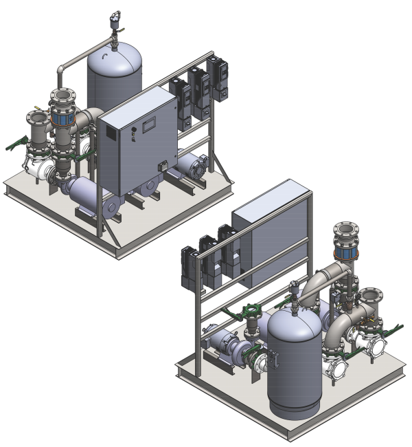
Renderings of the skid installed at the Haartz facility.
Operational Lessons and Carbon Emission Reduction
As the system entered real-world operation, the company identified several important lessons related to heat recovery performance. The original design assumptions were based on production levels from 2024, when portions of the plant ran continuously. Subsequent production slowdowns altered chilled water return conditions in ways that impacted heat recovery availability.
“There’s been a bit of a slowdown of production in the area this header serves, and when they are not running, they isolate valves off. What that does is basically starve the available heat we can put into the unit,” Blanchard said.
Because heat pumps depend entirely on available thermal energy transfer, reduced process load directly affected heating performance.
“Heat pumps work off of an exchange of heat. We’re moving heat from one location to the other using the electrical input and the refrigerant. If there’s no heat to move, there’s no heat that we can generate,” he added.
The system required additional operational coordination to ensure enough process flow remained available during reduced production times. Even with those operational refinements underway, the project demonstrated the viability of large-scale industrial heat recovery using water source heat pump technology. Blanchard viewed the installation as an important proof-of-concept for broader industrial applications.
“This particular project is a strong fit for customers with constant air makeup needs, or if there’s a hot water demand we could offset boiler gas use with this type of technology. If there’s a constant process demand, this is a good example of real savings,” Blanchard said. “This isn’t smoke and mirrors. It’s real identifiable, calculable savings, and the applications could be wide and varied.”
The project’s cost was $749,985, which includes the new chiller and makeup air unit. National Grid provided a rebate for $562,936, funding 75% of the cost. The primary goal of the project was electrification and decarbonization, and the resulting system is estimated to reduce carbon emissions by 111 tons each year.
For the company, this customer’s installation established a new category of industrial electrification work combining process cooling, HVAC integration and waste heat recovery into a unified system architecture.
“This type of technology is truly useful,” Blanchard said. “It’s nice to see the state’s utilities are incentivizing it, but even if they’re not, the calculable savings are real for this type of technology.”
About Process Cooling Systems
Founded in 1963, Process Cooling Systems has grown into a trusted partner for industrial manufacturers across a wide variety of sectors, including plastics, heat treatment, food and chemical processing. The company specializes in designing, installing and servicing custom process water systems combining energy efficiency, performance and long-term reliability. For more information, visit https://www.processcooling.net.
To read more Plastics Industry Articles, visit https://coolingbestpractices.com/industries/plastics-and-rubber.
Visit our Webinar Archives to listen to expert presentations on Plastics Industry cooling needs at https://coolingbestpractices.com/magazine/webinars.